Laptop Repair Guy points out that Toshiba has issued a warranty extension resulting from a class action lawsuit. As far as I can tell (I’m not a lawyer so better check for yourself) I’m out of luck since I’m in Canada but definitely better to have Toshiba fix it for free than try yourself.
My Toshiba Satellite A70 started having power problems several weeks ago. Although the power cord was plugged in, the computer was not charging and was draining the battery. The little ‘plugged-in’ LED would come up but the battery status LED would still show power coming from the battery. I could jiggle the power cord and it would come back up so I ignored it and got used to jiggling. Unfortunately, the power got more and more touchy and I spent more and more time jiggling the stupid power cord. I first guessed it must be something with my power adaptor but (after cutting open the outer wrap of the cord), I finally put it together that the ‘plugged-in’ LED was coming on but not the battery charging light. This seemed pretty odd. So I finally went out and bought a multimeter. For $20 it was a really good investment and I wish I would have bought one several hours of jiggling frustration earlier. Anyway after the multimeter showed the cord was giving the appropriate 19V without any interruptions, I finally got the bright idea to google the problem and found out that this is a common problem for the A70. Although I have soldered maybe once in my life, the repair didn’t look all that difficult so I thought I’d give it a shot. I ran out and grabbed a crappy Radio Shack iron for $15 and a pack of resistors and circuit board to practice on for $10. You could skip the practice if you were already confident in soldering.
The website How to dismantle a Toshiba A70 is invaluable for this task. I just thought I’d add a few notes to their steps:
- Step 2 includes “Remove the metal brace and the wireless card.” I think this could have been a bit more descriptive. There are two wires running fromt the card up through a hole in the motherboard. I’m pretty paranoid and I couldn’t quite work up the guts to disconnect these until I already had the screen off. But you really don’t have to worry. The wires end in little connectors that pop on and off easily enough. Also when you disconnect the wires, make sure to note which one goes where. I forgot to and took a guess. Since my internet, isn’t reversed I’m assuming I was correct.
- Steps 6 and 7, “Remove the securing strip,” are a real pain. I took the little strip above the keyboard off three or four times and every time it gave me a hassle. It seems to help if you get the bottom keyboard side off first and then work on the top. It’s amazing how well it holds on for just being little plastic tabs.
- When following step 10, “Disconnect the keyboard cable from the system board,” there are little lock things on each side of the keyboard ribbon. Don’t forget to unlock these when taking it out and relock them when putting it back. I forgot to relock them and spent a few anxious moments trying to figure out why only half my keyboard was working.
- Step 20, “Carefully remove the system board from the base,” is even more of a pain than removing the securing strip. It’s sort of the same idea only with a $1000 dollar motherboard instead of a $5 piece of plastic. The motherboard is really wedged in there. I found it easiest to start by getting the PC slot side out first. If you push in the little PC ejector button and sort of lever it and the i.LINK port with a screwdriver, you should be able to get it above the plastic. After that, a little lever action on the volume and headphone jacks on the other side and it should come out fairly easily. This took me about half an hour to figure out. An important note is that if you are certain the DC input jack is the problem you don’t even need to take out the motherboard. You could just solder the end of it with it in place. A good way to check this would be to wiggle the power connector from the outside and watch the pins of jack on the inside.
- One general point is that there are more than two types of screws. I saw long ones and short ones and assumed that there were only two types. But somewhere in there there is also a medium length screw. You would probably want to pay better attention to this than I did. My last hole didn’t fit my last screw. Luckily, it was only the hard drive cover and it already had one screw holding it in so I guess it will hold until something else breaks…
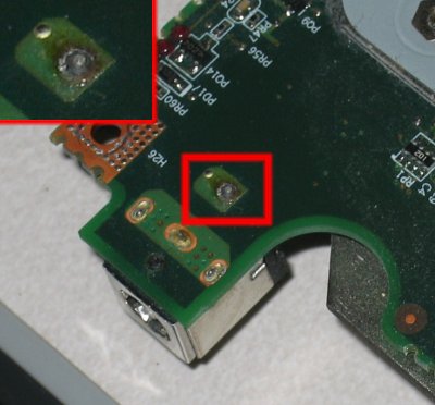
So once I finally got into the motherboard, I could see the rear pin of the power input jack moving freely in and out it’s hole on the motherboard. I’m not electrician but I assumed this was a bad thing.
So I fired up my fresh new soldering iron and after practicing with a few resistors, I finally worked up the guts to solder the loose jack. I ended up with a decent sized blob so I cut off some of the extra with some wire clippers. It’s worked for a week now so I guess it turned out ok. So in summary it took me, a complete novice at electronics, several hours to fix and cost $45 but I can use the tools again and I learned a lot about the inner working of my computer so I guess the only real cost was a bit of solder. If it breaks again (knock on wood), I might have to try this workaround.
Edit: Laptop Freak left a informative comment:
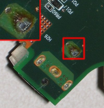
As you see on the photo above, the positive connector oxidized and almost black. If you put a fresh solder on the connector like this, the power jack problem will reappear very soon. I usually remove the power jack from the system board (with iron gun and solder sucker), clean oxidized pins on the power jack and pads on the motherboard and only after that resolder the power jack.
So I may be getting the chance to replace my missing screw sooner than I had hoped.
Update:Laptop Repair Guy now has a great step by step guide (complete with many pictures) to repairing the power jack.
Electrician | 06-Mar-11 at 9:28 pm | Permalink
I had the power jack problem on my A70 about before. Each time I messed with the jack it came undonelater. This time before I resoldered the jack/motherboard connection it worked!!
muhammad naeem khan | 26-Jul-11 at 2:39 am | Permalink
complained that his Toshiba Satellite A70 laptop doesn’t have video on LCD but the screen lights up when he turns on the laptop.
daniel | 02-Oct-11 at 12:01 pm | Permalink
how can i repair my toshiba satellite if i put my power in it dont not display and need i put it out it display please hepl.
manolo | 26-May-12 at 11:21 pm | Permalink
yo tube el mismo problema pero la solde y limpie los contactos y listo yo pense q solo a mi me havia dado este problema
Jake | 22-Jun-12 at 2:32 pm | Permalink
Daniel, lot’s of resources out there to answer your question. Good Luck!